| SHDesigns: Scott Henion's Welding pages. | Page hits: |
It can be modified for use on single phase and short-arc welding. It will be limited to about 220 amps when run off of single phase.
Note: If you are not sure how to do this modification, then do not attempt it. We are taking huge currents here and high-voltages. There is a risk of fire, eletricution or damaging the unit if not done properly.
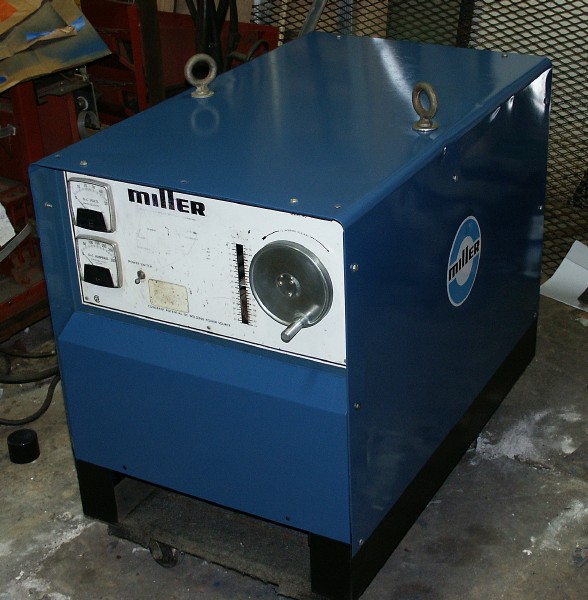 |
This is the CP-250TS described on this page. |
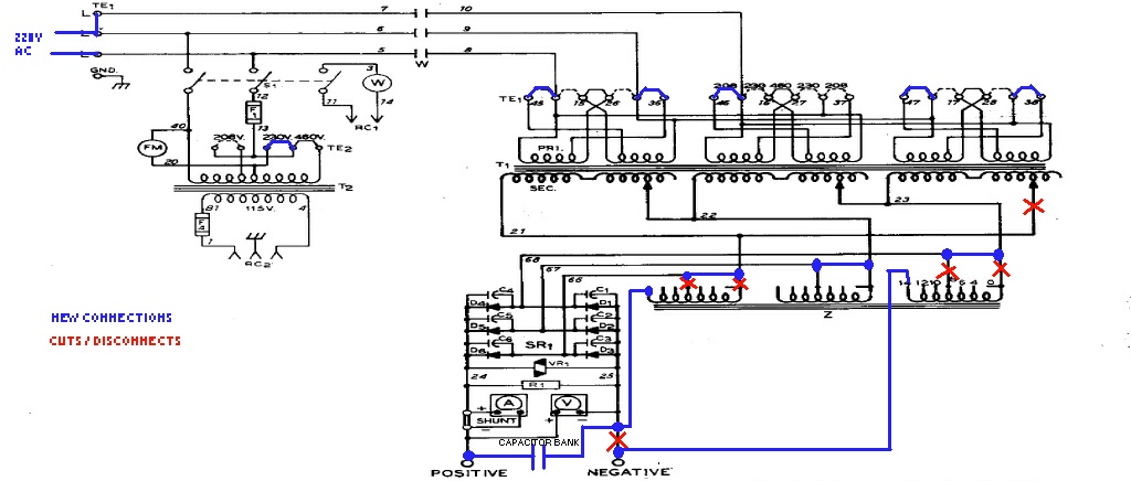
These modifications are for the later versions of the CP-250TS. These have a Wye-connected transformer. On the inside side door, there should be a schematic. You can also use the model and serial number and download the schematic from the Miller web site. The schematic should look as follows:
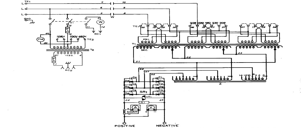
Note that there are two wires between each the upper windings. Earlier versions had one leg of all 3 windings tied together (that requires a different modification.)
First connect a 220V power source with one lead on TE3 (left terminal) and the other lead connected to both TE2 and TE1. This is shown below:
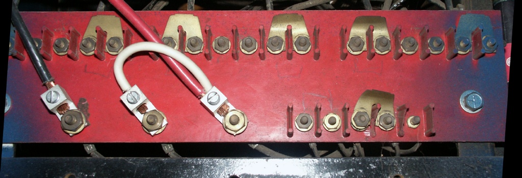
The top row of jumpers are set to 208V. The bottom set are connected for 230V. Note: some of the left terminals are cut off the picture. Each phase has 6 screw terminals in the top row; there is a blank spot between each phase. A jumper goes between the outer two of each set of terminals as show (left jumper is hidden.) Consult the manual if this is not clear. 208V is used as it increases the output a bit as we will lose some voltage going from 3 to 2 windings.
The bottom row selects the voltage for the contactor supply. This is set to 230V.
The settings above short out one of the transformer windings (not used.) I cant take a picture of this as the 750lb Airco is sitting on top of the miller and I can't remove the cover to take a picture. I found the supply tripped a breaker randomly as transients in the coils caused surge currents on the unused shorted phase.
Remove the cover, on the right side is the slider connections (blocks on the threaded rods.) The rightmost slider will have a heavy wire with #21 printed on it. Disconnect this wire, tape it up and cable-tie it out of the way.
That is all that is needed for single phase. The supply should work fine with a bit lower voltage (when dial set to 20V it will be about 18V.) Test it first before doing and further modifications. A 50 amp 220V breaker should be used.
The CP-250TS was made for spray-transfer welding. Short-arc (Dip Transfer) will work, but it does not really work well. The later version of the welder, the CP-252TS, added a separate reactor. There are 3 ways of adding a reactor:
You will need some #6 or larger wire. #4 would be better. These options are described in the following sections:
I made my own coils. One is shown below:
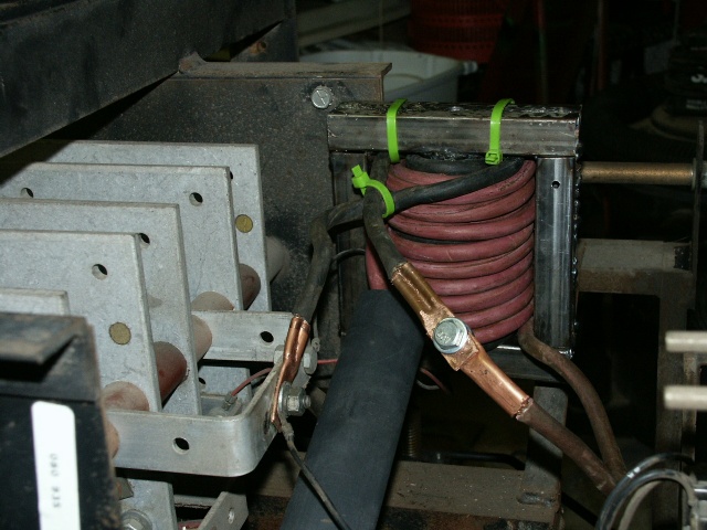
It is basically about 5" of 1.5" iron pipe wrapped in a steel frame. I used some small square tubing. 3" x 3/16" flat stock would work better. I have also used 2" mild-steel bar stock as a core but iron woks better. The actual inductance is not critical, more is usually better. The more reactance, the more heat will be in the weld and the weld pool will be more fluid providing flatter welds.
I used about 30 turns of #4 wire as a coil. I did not have enough in a single length, so it was wound in two sections; the connection between the two are shown in front of the coil. Solid wire would work best or even copper tubing with heat shrink over it. It should be #4 wire or heavier.
The coil is inserted in the '-' lead. It can be added externally if needed by connecting one lead to the - terminal and the work lead to the other coil wire.
To mount inside, locate a place to mount for the coil. Follow the '-' lead back from the from panel to the rectifier (aluminum plate.) Disconnect this lead and connect it to one leg of the coil. Connect the other leg to where the original - lead connected to the rectifier.
I made connection lugs from 1/4" ID copper tubing. Cut a length to about 2". Flatten half of it and drill a 1/4" hole. The wire can be inserted in the open end then crimped with a dull cold chisel. I then pound the end tighter, this double crimp provides a very tight connection. You can see the terminals in the above picture. Walmart sells #6 lugs in their department that sells lawn mower batteries.
This is not as easy. Inside the side door, locate the slope coils:
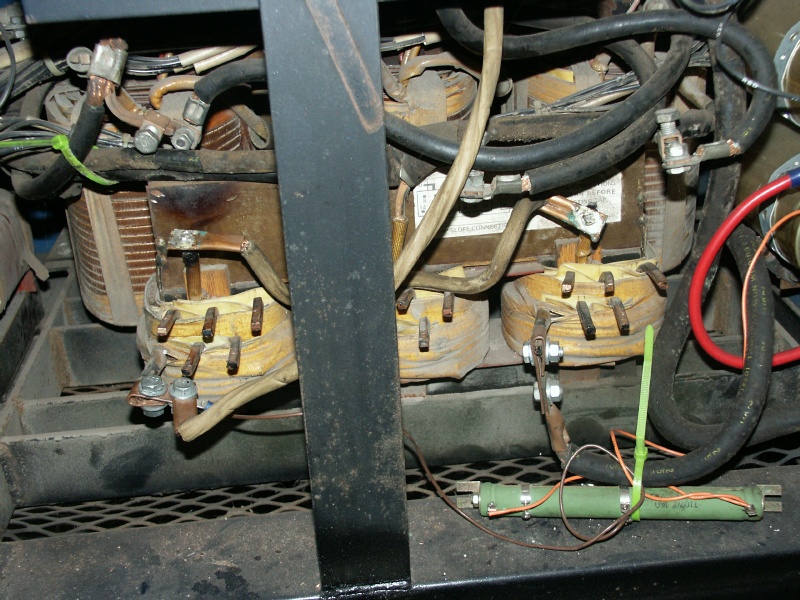
There are terminals marked 0 through 14 on each coil (there is a drawing on the coils.) First, set all jumpers to the #0 terminals. Then on the left and right coils, cut the lead just below the #0 terminal and bend forward (they run vertical up from the windings.) I find a cutoff wheel on a die grinder or Dremel best for this. You will need to support the #0 terminals as they may flop around. I cable-tied them out of the way.
Make a jumper out of heavy wire and connect the two #0 windings isolated earlier together. I used copper tubing crimped on the wire, drilled a hole, slipped them over the square wire and soldered them.
You will need to make terminals like were used before. I cut 1/4" ID copper tubing to about 3". I folded over 1" of the end over a 1/4 bolt. This formed a U that clamps on the terminal. A drawing is shown below:
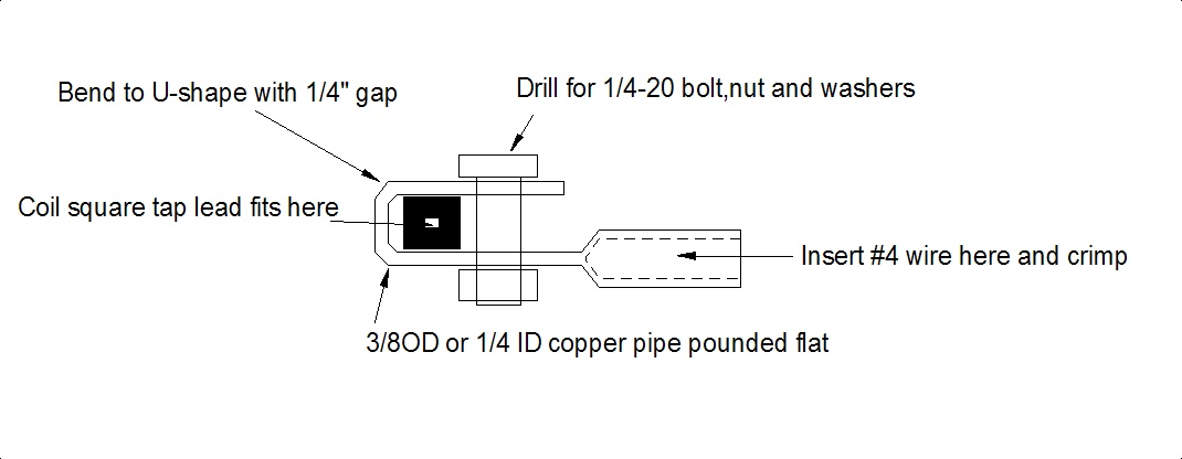
One of the terminals will be connected to one of the lugs on the - lead. This one will have the entire length pounded flat and a 1/4" hole drilled to bolt the wire to. It is shown in the right half of the picture connected to one of the windings with the heavy - lead bolted to it.
Make up a wire with one of the above lugs on one and and one with just a flat end with a hole on the other. This should reach from the rectifier plates to the left coil (white wire in picture.)
Disconnect the - lead from the rectifier assembly (follow lead back from - terminal.) Make up a lug and bolt it to the #14 terminal on the right coil.
Take the wire made earlier and connect one end to the bolt where the - lead used to go on the rectifier assembly. Connect the other end to the #14 terminal on the left coil.
That is it for the coil modifications. Note: you can vary the inductance; use lower numbered taps to reduce the inductance. I have tried various settings and the above works best.
When running on single phase, the output power is a rectified AC with a lot of ripple. This will decrease the arc stability a bit. Adding a bank of capacitors will smooth out the power and provide a smooth arc. Capacitance from 20,000 to 150,000 micro farads will work. More is better for a smooth arc at higher currents, but will increase the surge when the contactor turns on. I used 60,000 micro farads (uF).
A small motor run capacitor can be used (100 to 200uf.) That will increase the stability a bit but there will still be a "buzz" of the rectified AC.
One big capacitor will likely just burn up as we will be pulling huge currents through it. So, a bank of smaller capacitors is better. These need to be rated at 50 volts or higher. I used two, 30,000uF capacitors. On my DIY-welder, I used three, 23,000uf capacitors. I would have used 5, but I could not fit them. These should be "Computer Grade" or "Low ESR" capacitors. Each capacitor should be 20,000 to 30,000uf. Larger may not handle the current well.
The capacitors need to be connected together with a heavy copper or aluminum bar. I have used flattened 1/4" ID copper tubing or 1/2" x 1/8" aluminum stock.
The capacitors connect to the + and outputs of the rectifier assembly. #24 on the schematic is the - and #25 is the +. Be sure to connect the polarity right as the capacitors will literally explode if connected backwards.
Here is my bank connected:
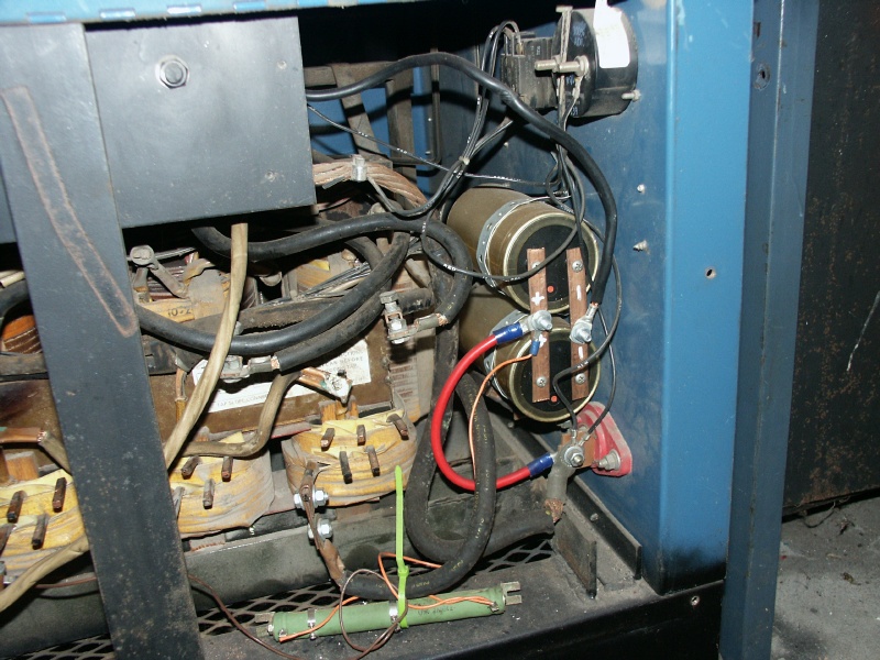
Note: the + side is connected to the output terminal as that is connected also to the + output of the rectifier.
Here is similar mod done on a CP-300 that was modified for single phase:
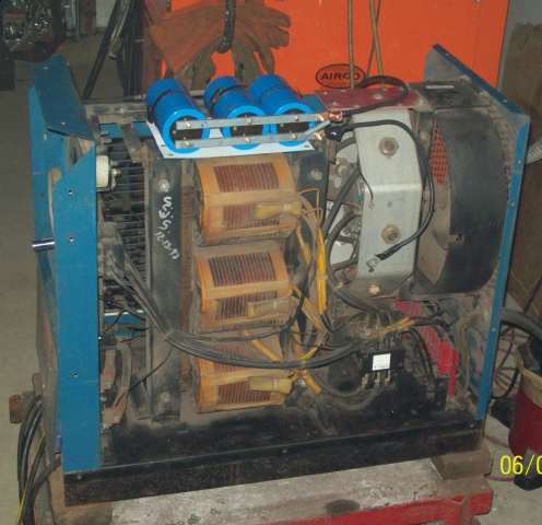 (Thanks to Ramon Mendosa for the
pictures.)
(Thanks to Ramon Mendosa for the
pictures.)
That was cleanly done.
Use suitable mounting straps. There are mounting brackets available, but they are not hard to make. Mine was simply pluming strapping bent around and bolted. I would have preferred to mount them in a better place, but I added them after installing the Airco on top of the Miller, so I did not want to haul out the engine hoist and remove it to allow access to the rest of the case.
The capacitors will increase the no-load voltage considerably. The meter will read much higher than the actual voltage when welding. This is due to the capacitors charging up to the peak voltage, but dropping to the average voltage when welding.
For safety, you should also add a bleeder resistor to discharge the caps when the contactor is off. A 150-ohm, 10 watt resistor should be placed across the capacitors. 300-ohm, 5 watt will do too. You can see the bleeder I added below the caps in the first picture below the "Adding a Capacitor Bank' banner. It is basically a 100 watt, 110 ohm resistor. A bit of overkill, but I had them.
At, 60,000uf, my effective voltage is considerably higher below about 100 amps. The capacitance will have less effect at higher currents.
Below is the schematic with the modifications shown